Figure shows two electrical circuits.
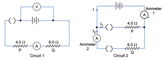
The batteries in circuit 1 and circuit 2 are identical.
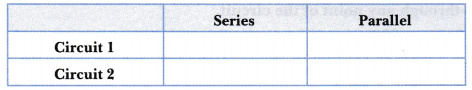
- Put ticks in the table below to describe the connections of the two resistors P and Q.
- The resistor P and Q are used as small electrical heaters.
State two advantages of connecting them as shown in circuit 2. - In circuit 1, the ammeter reads 1.2A when the switch is closed.
Calculate the reading of the voltmeter in this circuit. - The two switches in circuit 2 are closed. Calculate the combined resistance of the two resistors in this circuit.
- When the switches are closed in circuit 2, ammeter 1 reads 5 A and ammeter 2 reads 2A. Calculate
- current in resistor P,
- the power supplied to resistor Q,
- the energy transformed in resistor Q in 300s.
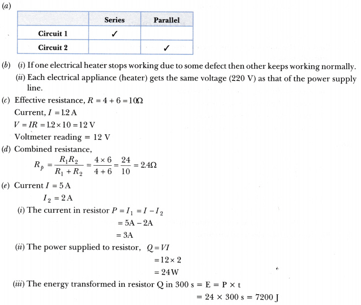
Answer: