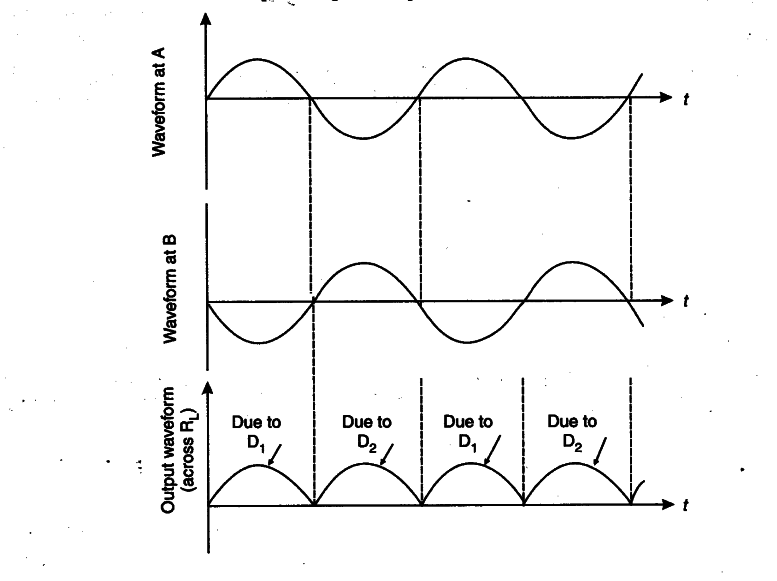
(a) Explain briefly, with the help of circuit diagram, the working of a full wave rectifier. Draw its input and output waveforms.
(b) Identify the logic gate equivalent to the circuit shown in the figure.
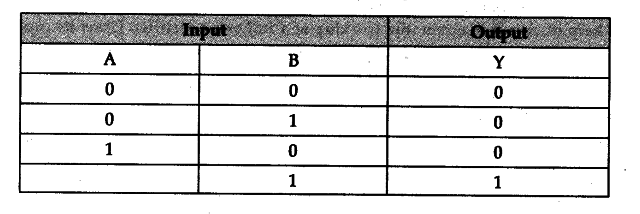
Draw the truth table for all possible values of inputs A and B.
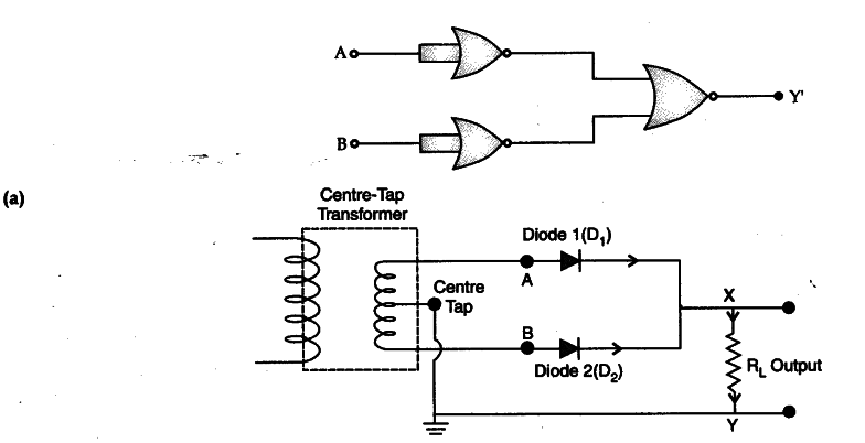
For half cycle of input a.c., one diode out of the two, will get forward biased and will conduct, while the other diode, being reverse biased, will not conduct. For other cycle of input signal, the diode, which was reverse biased, will get forward biased and will conduct, and the other diode will get reverse biased and will stop conducting. Hence we obtain a unidirectional output voltage for the positive as well as for negative half cycles.
(b) Identification : AND Gate
Truth Table